Welcome to our website!
 English
 +86 18702502991
 sales@xiqian-automation.com
best vibrator
pleated filter cartridge factory
high flow filter cartridge
large flow filter cartridge
membrane pleated filter cartridge
capsule filter suppliers
capsule filter 0.2 micron
capsule filter price
steel chastity cage
best chastity cage
men chastity cage
stainless steel chastity cage
silicone chastity cage
chastity cage device
best silicone chastity cage
water filter cartridge
masturbation cup
huge dildo
Categories

PRODUCTS


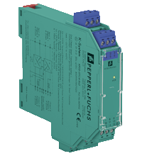
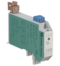
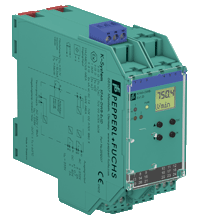
Universal Temperature Converter KFD2-UT2-Ex1
item No : KFD2-UT2-Ex1
- 1-channel isolated barrier
- 24 V DC supply (Power Rail)
- Thermocouple, RTD, potentiometer or voltage input
- Current output 0/4 mA ... 20 mA
- Sink or source mode
- Configurable by PACTware
- Line fault (LFD) and sensor burnout detection
- Up to SIL 2 acc. to IEC 61508/IEC 61511
Chat online :
 crystal94910
 +86 18702502991
 +86 18702502991
 sales@xiqian-automation.com
crystal94910+86 18702502991+86 18702502991sales@xiqian-automation.com
KFD2-UT2-Ex1
| General specifications | ||
|---|---|---|
| Signal type | Analog input | |
| Functional safety related parameters | ||
| Safety Integrity Level (SIL) | SIL 2 | |
| Supply | ||
| Connection | terminals 14+, 15- or power feed module/Power Rail | |
| Rated voltage | 20 ... 30 V DC | |
| Ripple | within the supply tolerance | |
| Power dissipation | ≤ 0.98 W | |
| Power consumption | max. 0.98 W | |
| Interface | ||
| Programming interface | programming socket | |
| Input | ||
| Connection side | field side | |
| Connection | terminals 1, 2, 3, 4 | |
| RTD |
type Pt10, Pt50, Pt100, Pt500, Pt1000 (EN 60751: 1995) type Pt10GOST, Pt50GOST, Pt100GOST, Pt500GOST, Pt1000GOST (6651-94) type Cu10, Cu50, Cu100 (P50353-92) type Ni100 (DIN 43760) |
|
| Measuring current | approx. 200 µA with RTD | |
| Types of measuring | 2-, 3-, 4-wire connection | |
| Lead resistance | max. 50 Ω per line | |
| Measurement loop monitoring | sensor breakage, sensor short-circuit | |
| Thermocouples |
type B, E, J, K, N, R, S, T (IEC 584-1: 1995) type L (DIN 43710: 1985) type TXK, TXKH, TXA (P8.585-2001) |
|
| Cold junction compensation | external and internal | |
| Measurement loop monitoring | sensor breakage | |
| Potentiometer | 0 ... 20 kΩ (2-wire connection), 0.8 ... 20 kΩ (3-wire connection) | |
| Voltage | selectable within the range -100 ... 100 mV | |
| Input resistance | ≥ 1 MΩ (-100 ... 100 mV) | |
| Output | ||
| Connection side | control side | |
| Connection | output I: terminal 7: source (-), sink (+), terminal 8: source (+), terminal 9: sink(-) | |
| Output | Analog current output | |
| Current range | 0 ... 20 mA or 4 ... 20 mA | |
| Fault signal | downscale 0 or 2 mA, upscale 21.5 mA (acc. NAMUR NE43) | |
| Source |
load 0 ... 550 Ω open-circuit voltage ≤ 18 V |
|
| Sink |
Voltage across terminals 5 ... 30 V. If the current is supplied from a source > 16.5 V, series resistance of ≥ (V - 16.5)/0.0215 Ω is needed, where V is the source voltage. The maximum value of the resistance is (V - 5)/0.0215 Ω. |
|
| Transfer characteristics | ||
| Deviation | ||
| After calibration |
Pt100: ± (0.06 percent of measurement value in K + 0.1 percent of span + 0.1 K (4-wire connection)) thermocouple: ± (0.05 percent of measurement value in °C + 0.1 percent of span + 1 K (1.2 K for types R and S)) , includes ± 0.8 K fault of the cold junction compensation (CJC) mV: ± (50 µV + 0.1 percent of span) potentiometer: ± (0.05 percent of full scale + 0.1 percent of span, (excludes faults due to lead resistance)) |
|
| Influence of ambient temperature |
Pt100: ± (0.0015 percent of measurement value in K + 0.006 percent of span)/K ΔTamb*) thermocouple: ± (0.02 K + 0.005 percent of measurement value in °C + 0.006 percent of span)/K ΔTamb*)), influence of cold junction compensation (CJC) included mV: ± (0.01 percent of measurement value + 0.006 percent of span)/K ΔTamb*) potentiometer: ± 0.006 percent of span/K ΔTamb*) *) ΔTamb = ambient temperature change referenced to 23 °C (296 K) |
|
| Influence of supply voltage | < 0.01 percent of span | |
| Influence of load | ≤ 0.001 percent of output value per 100 Ω | |
| Reaction time |
worst case value (sensor breakage and/or sensor short circuit detection enabled) mV: 1 s, thermocouples with CJC: 1.1 s, thermocouples with fixed reference temperature: 1.1 s, 3- or 4-wire RTD: 920 ms, 2-wire RTD: 800 ms, Potentiometer: 2.05 s |
|
| Galvanic isolation | ||
| Output/supply, programming input |
functional insulation, rated insulation voltage 50 V AC There is no electrical isolation between the programming input and the supply. The programming cable provides galvanic isolation so that ground loops are avoided. |
|
| Indicators/settings | ||
| Display elements | LEDs | |
| Configuration | via PACTware | |
| Labeling | space for labeling at the front | |
| Directive conformity | ||
| Electromagnetic compatibility | ||
| Directive 2014/30/EU | EN 61326-1:2013 (industrial locations) | |
| Conformity | ||
| Electromagnetic compatibility | NE 21:2006 | |
| Degree of protection | IEC 60529:2001 | |
| Protection against electrical shock | UL 61010-1:2004 | |
| Ambient conditions | ||
| Ambient temperature | -20 ... 60 °C (-4 ... 140 °F) | |
| Mechanical specifications | ||
| Degree of protection | IP20 | |
| Connection | screw terminals | |
| Mass | approx. 130 g | |
| Dimensions | 20 x 119 x 115 mm (0.8 x 4.7 x 4.5 inch) (W x H x D) , housing type B2 | |
| Mounting | on 35 mm DIN mounting rail acc. to EN 60715:2001 | |
| Data for application in connection with hazardous areas | ||
| EU-type examination certificate | CESI 04 ATEX 143 | |
| Marking |
 II (1)G [Ex ia Ga] IIC II (1)D [Ex ia Da] IIIC I (M1) [Ex ia Ma] I II (1)G [Ex ia Ga] IIC II (1)D [Ex ia Da] IIIC I (M1) [Ex ia Ma] I
|
|
| Input | Ex ia | |
| Inputs | terminals 1, 2, 3, 4 | |
|
Voltage |
9 V | |
|
Current |
22 mA | |
|
Power |
50 mW | |
| Analog outputs, power supply, collective error | ||
| Maximum safe voltage | 250 V (Attention! This is not the rated voltage.) | |
| Interface | ||
| Maximum safe voltage | 250 V (Attention! The rated voltage is lower.), RS 232 | |
| Certificate | TÜV 02 ATEX 1797 X | |
| Marking |
II 3G Ex nA II T4
|
|
| Galvanic isolation | ||
| Input/Other circuits | safe electrical isolation acc. to IEC/EN 60079-11, voltage peak value 375 V | |
| Directive conformity | ||
| Directive 2014/34/EU | EN 60079-0:2012+A11:2013 , EN 60079-11:2012 , EN 60079-15:2010 , EN 50303:2000 | |
| International approvals | ||
| UL approval | ||
| Control drawing | 116-0410 | |
| CSA approval | ||
| Control drawing |
116-0314 (cCSAus) 116-0347 |
|
| IECEx approval | ||
| IECEx certificate |
IECEx TUN 07.0003 IECEx CML 16.0126X |
|
| IECEx marking |
[Ex ia Ga] IIC [Ex ia Da] IIIC [Ex ia Ma] I Ex nA IIC T4 Gc |
|
| General information | ||
| Supplementary information | Observe the certificates, declarations of conformity, instruction manuals, and manuals where applicable. For information see www.pepperl-fuchs.com. | |
Classifications
| System | Classcode |
|---|---|
| ECLASS 11.0 | 27210129 |
| ECLASS 10.0.1 | 27210129 |
| ECLASS 9.0 | 27210129 |
| ECLASS 8.0 | 27210190 |
| ECLASS 5.1 | 27210107 |
| ETIM 8.0 | EC002919 |
| ETIM 7.0 | EC002919 |
| ETIM 6.0 | EC002919 |
| ETIM 5.0 | EC001485 |
| UNSPSC 12.1 | 32101514 |
Related Products


 NEWSLETTER
 +86 18702502991
 +86 18825896673

CopyRight 2022 Shanghai XiQian Automation Technology Co.,Ltd


