Welcome to our website!
 English
 +86 18702502991
 sales@xiqian-automation.com
best vibrator
pleated filter cartridge factory
high flow filter cartridge
large flow filter cartridge
membrane pleated filter cartridge
capsule filter suppliers
capsule filter 0.2 micron
capsule filter price
steel chastity cage
best chastity cage
men chastity cage
stainless steel chastity cage
silicone chastity cage
chastity cage device
best silicone chastity cage
water filter cartridge
masturbation cup
huge dildo
Categories


PRODUCTS

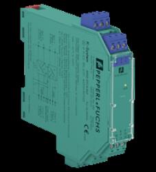
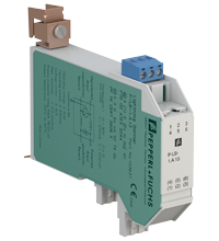
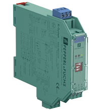
P+F SMART Transmitter Power Supply KCD2-STC-Ex1
item No : KCD2-STC-Ex1
- 1-channel isolated barrier
- 24 V DC supply (Power Rail)
- Input for 2-wire
Chat online :
 crystal94910
 +86 18702502991
 +86 18702502991
 sales@xiqian-automation.com
Technical Parameter : KCD2-STC-Ex1
| General specifications | ||
|---|---|---|
| Signal type | Analog input | |
| Functional safety related parameters | ||
| Safety Integrity Level (SIL) | SIL 2 | |
| Systematic capability (SC) | SC 3 | |
| Supply | ||
| Connection | Power Rail or terminals 9+, 10- | |
| Rated voltage | 19 ... 30 V DC | |
| Ripple | ≤ 10 percent | |
| Rated current | ≤ 45 mA at 24 V and 20 mA source mode output | |
| Power dissipation | ≤ 800 mW | |
| Power consumption | ≤ 1.1 W | |
| Input | ||
| Connection side | field side | |
| Connection | terminals 1+, 2-; 3+, 4- | |
| Input signal | 4 ... 20 mA limited to approx. 26 mA | |
| Open circuit voltage/short-circuit current | terminals 1+, 2-: 22 V / 26 mA | |
| Voltage drop | terminals 3+, 4- : approx. 5 V | |
| Available voltage | terminals 1+, 2-: ≥ 15 V at 20 mA ; ≥ 18 V at 4 mA | |
| Output | ||
| Connection side | control side | |
| Connection |
terminals 5-, 6+ terminals 5-, 8+ for HART resistor |
|
| Load | 0 ... 350 Ω (source mode) | |
| Output signal |
4 ... 20 mA or 1 ... 5 V (on 250 Ω, 0.1 percent internal shunt) 4 ... 20 mA (sink mode), operating voltage 10 ... 30 V |
|
| Ripple | 20 mV rms | |
| Transfer characteristics | ||
| Deviation |
at 20 °C (68 °F) < 0.1 percent of full scale, incl. non-linearity and hysteresis (source mode and sink mode 4 ... 20 mA) ≤ ± 0.2 percent incl. non-linearity and hysteresis (source mode 1 ... 5 V) |
|
|
|
Influence of ambient temperature |
< 2 µA/K (-20 ... 70 °C (-4 ... 158 °F)); < 4 µA/K (-40 ... -20 °C (-40 ... -4 °F)) (source mode and sink mode 4 ... 20mA) < 0.5 mV/K (-20 ... 70 °C (-4 ... 158 °F)); < 1 mV/K (-40 ... -20 °C (-40 ... -4 °F)) (source mode 1...5 V) |
| Frequency range |
field side into the control side: bandwidth with 0.5 Vpp signal 0 ... 3 kHz (-3 dB) control side into the field side: bandwidth with 0.5 Vpp signal 0 ... 3 kHz (-3 dB) |
|
| Settling time | ≤ 50 ms | |
| Rise time/fall time | ≤ 10 ms | |
| Galvanic isolation | ||
| Input/Output | basic insulation according to IEC/EN 61010-1, rated insulation voltage 300 Veff | |
| Input/power supply | reinforced insulation according to IEC/EN 61010-1, rated insulation voltage 300 Veff | |
| Output/power supply | basic insulation according to IEC/EN 61010-1, rated insulation voltage 300 Veff | |
| Indicators/settings | ||
| Display elements | LED | |
| Control elements | DIP switch | |
| Configuration | via DIP switches | |
| Labeling | space for labeling at the front | |
| Directive conformity | ||
| Electromagnetic compatibility |
|
|
|
|
Directive 2014/30/EU | EN 61326-1:2013 (industrial locations) |
| Conformity | ||
| Electromagnetic compatibility |
NE 21:2017 EN 61326-3-2:2018 |
|
| Degree of protection | IEC 60529:2001 | |
| Protection against electrical shock | UL 61010-1:2012 | |
| Ambient conditions | ||
| Ambient temperature | -40 ... 70 °C (-40 ... 158 °F) | |
| Mechanical specifications | ||
| Degree of protection | IP20 | |
| Connection | screw terminals | |
| Mass | approx. 100 g | |
| Dimensions | 12.5 x 119 x 114 mm (0.5 x 4.7 x 4.5 inch) (W x H x D) , housing type A2 | |
| Mounting | on 35 mm DIN mounting rail acc. to EN 60715:2001 | |
| Data for application in connection with hazardous areas | ||
| EU-type examination certificate | CESI 06 ATEX 021 | |
|
|
Marking |
 II (1)G [Ex ia Ga] IIC II (1)D [Ex ia Da] IIIC I (M1) [Ex ia Ma] I II (1)G [Ex ia Ga] IIC II (1)D [Ex ia Da] IIIC I (M1) [Ex ia Ma] I
|
|
|
Input | Ex ia |
| Supply |
|
|
|
|
Maximum safe voltage | 250 V AC (Attention! Um is no rated voltage.) |
| Equipment | terminals 1+, 2- | |
|
|
Voltage |
25.2 V |
|
|
Current |
100 mA |
|
|
Power |
630 mW |
|
|
Internal capacitance |
5.7 nF |
|
|
Internal inductance |
negligible |
| Equipment | terminals 3+, 4- | |
|
|
Voltage |
30 V |
|
|
Current |
128 mA |
|
|
Voltage |
7.2 V |
|
|
Current |
100 mA |
|
|
Power |
25 mW |
|
|
Internal capacitance |
5.7 nF |
|
|
Internal inductance |
negligible |
| Certificate | CESI 19 ATEX 021 X | |
|
|
Marking |
II 3G Ex ec IIC T4 Gc
|
| Galvanic isolation |
|
|
|
|
Input/Output | safe electrical isolation acc. to IEC/EN 60079-11, voltage peak value 375 V |
|
|
Input/power supply | safe electrical isolation acc. to IEC/EN 60079-11, voltage peak value 375 V |
| Directive conformity |
|
|
|
|
Directive 2014/34/EU | EN 60079-0:2012+A11:2013 , EN 60079-11:2012 , EN 60079-7:2015 |
| International approvals | ||
| FM approval |
|
|
|
|
FM certificate | FM 18 CA 0116 X , FM 19 US 0117 X |
|
|
Control drawing | 116-0469 (cFMus) |
| UL approval | E106378 | |
|
|
Control drawing | 116-0459 (cULus) |
| IECEx approval |
|
|
|
|
IECEx certificate | IECEx CES 06.0001X |
|
|
IECEx marking |
[Ex ia Ga] IIC , [Ex ia Da] IIIC , [Ex ia Ma] I Ex ec IIC T4 Gc |
| General information | ||
| Supplementary information | Observe the certificates, declarations of conformity, instruction manuals, and manuals where applicable. For information see www.pepperl-fuchs.com. | |
Classifications
| System | Classcode |
|---|---|
| ECLASS 11.0 | 27210119 |
| ECLASS 10.0.1 | 27210119 |
| ECLASS 9.0 | 27210119 |
| ECLASS 8.0 | 27210119 |
| ECLASS 5.1 | 27210119 |
| ETIM 8.0 | EC001485 |
| ETIM 7.0 | EC001485 |
| ETIM 6.0 | EC001485 |
| ETIM 5.0 | EC001485 |
| UNSPSC 12.1 | 32101514 |
Related Products


 NEWSLETTER
 +86 18702502991
 +86 18825896673

CopyRight 2022 Shanghai XiQian Automation Technology Co.,Ltd


